Wheels & Tread
Configured visual inspection of tread regions for indications such as shelling, flats, surface damage and irregular wear patterns.
MVIS combines synchronized industrial imaging, computer vision, optical sensing and configurable analytics to examine moving railway assets, highlight potential abnormalities and preserve the visual evidence needed for review.
Instead of treating inspection as a collection of disconnected photographs, MVIS is designed as a coordinated inspection workflow. The system acquires repeatable views of defined rolling-stock zones, processes the captured information and turns relevant observations into traceable inspection events.
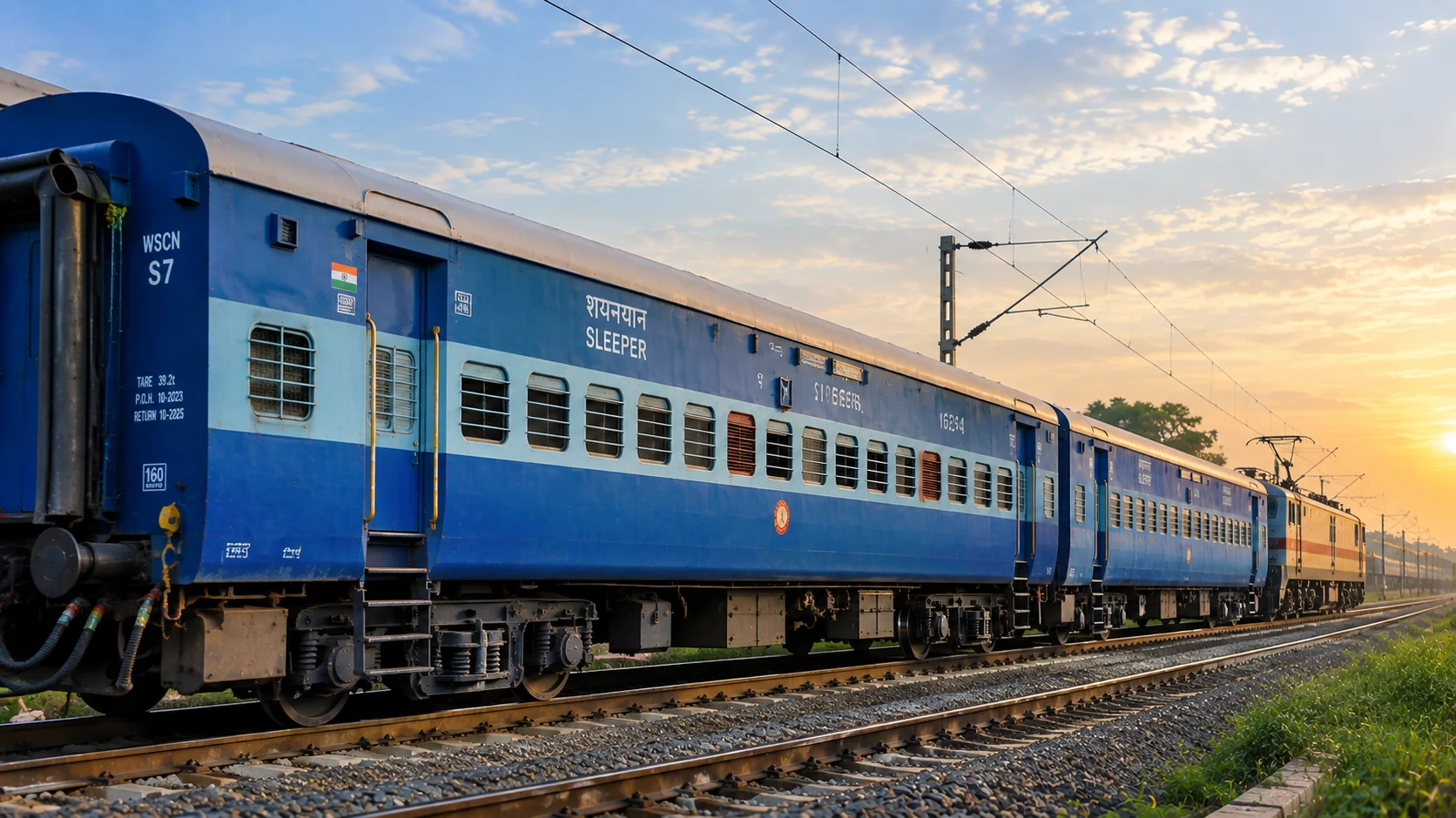
Machine vision creates a repeatable digital layer around the physical inspection process.
As a coach, wagon or other rolling-stock asset passes through the inspection environment, synchronized acquisition systems capture configured zones from appropriate viewpoints. The software pipeline can enhance imagery, identify regions of interest, apply configured AI models or rule-based checks and associate observations with train and inspection context.
This approach is intended to help inspection teams focus attention on relevant regions rather than manually searching through large volumes of images. Every configured finding can retain the source image, inspection location, timestamp and event context needed for later review.
The inspection scope is configurable to the asset, deployment environment and approved inspection objective. MVIS can be structured around individual components, zones or complete visual examination workflows.

A rolling-stock inspection system must deal with different component shapes, viewing angles, lighting conditions and asset configurations. MVIS provides a framework for defining the regions that matter and associating each region with its own inspection logic.
Depending on the deployment, coverage may include wheels and tread surfaces, bogies and suspension elements, underframe components, body panels and fittings, coupling interfaces, doors and other visible exterior features.
Configured visual inspection of tread regions for indications such as shelling, flats, surface damage and irregular wear patterns.
Visible bogie frames, springs, suspension elements and associated components can be included in the inspection scope.
Defined underframe zones can be captured repeatedly to highlight visible damage, displacement, missing parts or other configured conditions.
Exterior panels, doors, windows, fittings, fasteners and other visible body features can be monitored.
Coupling regions and associated interfaces can be examined for configured damage, abnormal position or missing hardware.
Optical and visual sensing can support configured checks for abnormal load profile and distribution.
Defect classes are configured for the intended application. The examples below show how a finding can be described, what automated vision can contribute and how the observation can move toward authorized verification.
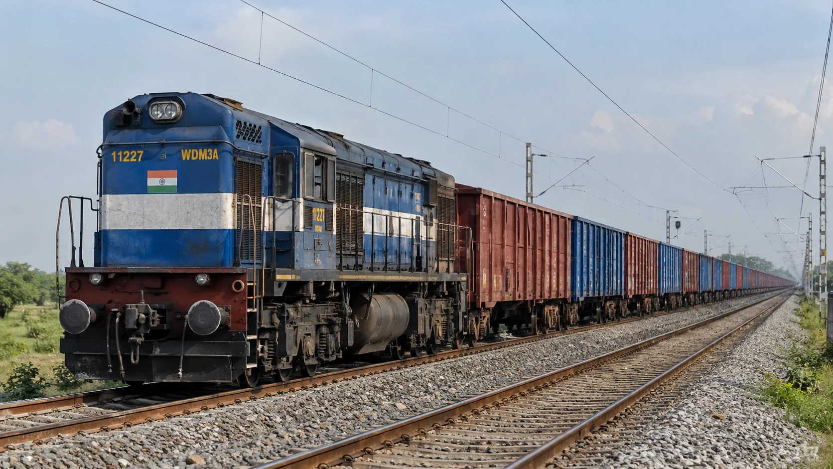
Automation is an inspection aid; final disposition remains with authorized railway personnel and applicable standards.
What it is: localized loss or spalling of material from the wheel tread.
MVIS contribution: configured tread analysis can highlight suspicious surface patterns and retain image evidence for review.
Typical response: verify against the applicable wheel-condition criteria and authorized maintenance process.
What it is: a localized flattened region on the wheel tread associated with wheel sliding.
MVIS contribution: visual anomaly detection can identify configured flat-like tread patterns.
Typical response: confirm condition and dimensions using the approved railway inspection procedure.
What it is: a visible surface indication that may require engineering verification.
MVIS contribution: high-resolution imaging can highlight suspicious regions for closer examination.
Typical response: physical inspection and disposition under the applicable safety procedure.
What it is: progressive or irregular change in wheel tread or profile condition.
MVIS contribution: configured visual indicators can be monitored and linked to inspection history.
Typical response: profile or dimensional verification against approved limits.
What it is: visible wear, displacement, damage or other configured brake-component condition.
MVIS contribution: defined brake zones can be captured and checked for configured visual abnormalities.
Typical response: component verification and the applicable brake maintenance procedure.
What it is: visible damage, deformation, displacement or missing components in defined underframe zones.
MVIS contribution: repeatable views can help identify and document configured patterns.
Typical response: detailed physical examination and engineering disposition.
What it is: visible damage, abnormal position or missing hardware around the coupling interface.
MVIS contribution: the coupler region can be inspected and associated with visual evidence.
Typical response: physical verification and rectification under the applicable procedure.
What it is: abnormal load distribution or an asymmetric loading profile.
MVIS contribution: optical sensing can support configured profile and distribution checks.
Typical response: verify the load and correct it under the governing loading procedure.
The workflow is designed to connect physical train movement with synchronized capture, analytics, evidence and human verification.
Identify the approaching asset and initiate the configured inspection sequence.
Acquire synchronized images and sensor information from defined zones.
Enhance imagery and prepare the data for analysis.
Apply configured computer vision, AI or rule-based checks.
Generate a structured event with relevant visual context.
Support authorized personnel in review and maintenance action.
Explore MVIS applications, technology and deployment architecture for automated railway inspection.